About a week ago I came accross one of Ange's pages (https://code.google.com/p/corkami/wiki/x86oddities?wl=en). Before that point I only knew him as a major contributor to my favorite zine (PoC||GTFO) and author of some very useful technical info-graphics; his ELF diagram jump started my ability to create my m2elf.pl script. Looking at his x86 oddities page, it looks like we have independently crossed streams on some of our research. There are a couple of nuggets on his page that slipped past my radar when reading the Intel manual. This post is about starting with one of the tid-bits on his page, and then getting side-tracked into another cool redundancy.
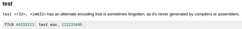
From the Corkami (Ange's) website:
In the context of Ange's TEST example, the proper machine encoding of test eax, 11223344h in the context of the f7 opcode should be: f7c0 44332211. TEST r/m32,imm32 is F7 /0, the f7c8 machine code above would be part of F7 /1, which is undocumented in the Intel manual (although, turns out it works as TEST as well). Also for the record, f6c0 is the correct TEST r/m8,imm8 of this variety, and f6c8 also works for 8-bit. Undocumented code exploration will be a topic I will likely post on in the near future (most likely starting with this TEST). So this is a pretty neat example of an undocumented redundancy.
...And then I looked up a little at the documentation to see the TEST EAX, imm32 encoding. First of all, TEST is just one in about 9 instructions that have this specific redundancy. Any instruction that has both:
OP EAX, imm32
and
OP r/m32, imm32
have a redundancy. This becomes obvious when you realize r/m32 can just as well be EAX. And though it will become clear soon, the machine code for each OP is different. This allows us to do familiar (for this blog) tricks to encode identical assembly with different machine code (one of my favorite things to do).
Below are the Intel manual descriptions of each:
![]()
![]()
Before going into the other 8 instructions, lets break down what's going on with our TEST instruction. We have two different machine encodings for this. The first one is as straight forward as it gets. TEST EAX, imm32 is represented as 'A9 id' where 'id' is the 'immediate double'. So 'A955555555' would be 'TEST EAX, 55555555h'.
The next encoding is TEST r/m32, imm32. Instead of just assuming we are testing the immediate value with EAX, we could use other registers and even memory pointers. This encoding is very similar to the usual ModR/M byte that we are used to, but with some important differences. Usually the ModR/M byte is Mod + r/m + r/m (but to be clear, one of the r/m's does not have an m; as there are no memory-to-memory operations). In this case, it is Mod + Instruction + r/m followed by the immediate data. In the case of TEST r/m32,imm32, the machine opcode is F7, but F7 is shared with instructions other than just test, which is why we have to specify which instruction in this ModR/M-like byte.
To illustrate the Opcode /[0-7] Notation, this byte (8 bits) is broken out like this:
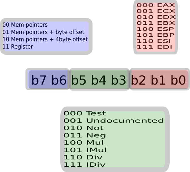
As always, Mod is our typicall 2 bit value, where binary 11 puts us in 'register land' (not memory pointers). our r/m is the standard eax, ecx, edx, ebx, esp, ebp, esi, edi (so the last 3 bits; for 8 distinct values). This leaves us with 3 bits in the middle of that to specify which of the 8 instructions represented by the F7 machine instruction we want to use. For the record, using F7, those 8 instructions are:
test, undocumented, not, neg, mul, imul, div, idiv
So whenever you see something like F7 /0 (or /1, /2, /3, /4, /5, /6, and /7), this number after the slash is a decimal representation of this 3-bit value in the middle of this byte. And F7 /1 is the basis of Ange's observation. Again, it turns out it is also 'Test.'
So if those bits were 000, we would be using test, if the bits were 011 (3) it would be neg. Say we had F7 D2. This is one of those times where looking at binary is pretty useful. Let's break D2 down into binary at 2 bits, 3 bits, and 3 bits; for Mod, Instruction, and R/M: 11 010 010. This is where the diagram above may be useful. The 11 Mod puts us in 'register-land'. The 010 is 2 counting from zero, so really the 3rd instruction in our list of the 8 instructions is 'not'. The 010 r/m (register in this case) would be edx (again, 3rd in the list of registers as layed out in the list of 8 registers above).
So our goal is to use F7 for the TEST instruction and with the redundant EAX register. This is 11 for Mod, 000 for the Instruction (TEST), and 000 for the EAX register. This gives us F7C0, and this would be followed by our 4 bytes of immediate data. So:
A955555555 = F7C055555555
(at the high level of assembly at least).
I guess that was a lot of detail for the quick couple of lines on Ange's page.
But wait, there's more. I started by saying that there are 8 more instructions that use this same redundant encoding. They are: ADC, ADD, AND, CMP, OR, SBB, SUB, and XOR. Furthermore, this isn't just restricted to the 32 bit variety, there is dedicated machine code (without using prefixes) for 8 bit encodings as well. And yes, with prefixes, there are modified 16 bit and 64 bit encodings. This gives us 36 different pairs of equivilant assembly with completely different machine code.
Below are 4 edb screenshots of the 9 different instructions (one for each 8-bit, 16-bit, 32-bit, and 64-bit):


Stay tuned for more posts in the series of assembly being to high-level. Ange triggered me on a couple more things that I have previously discovered (one of which I attempted to get Intel to correct their documentation, but for reasons, I doubt they will). So thank you Ange, for the inspiration to blast more machine into this blog.